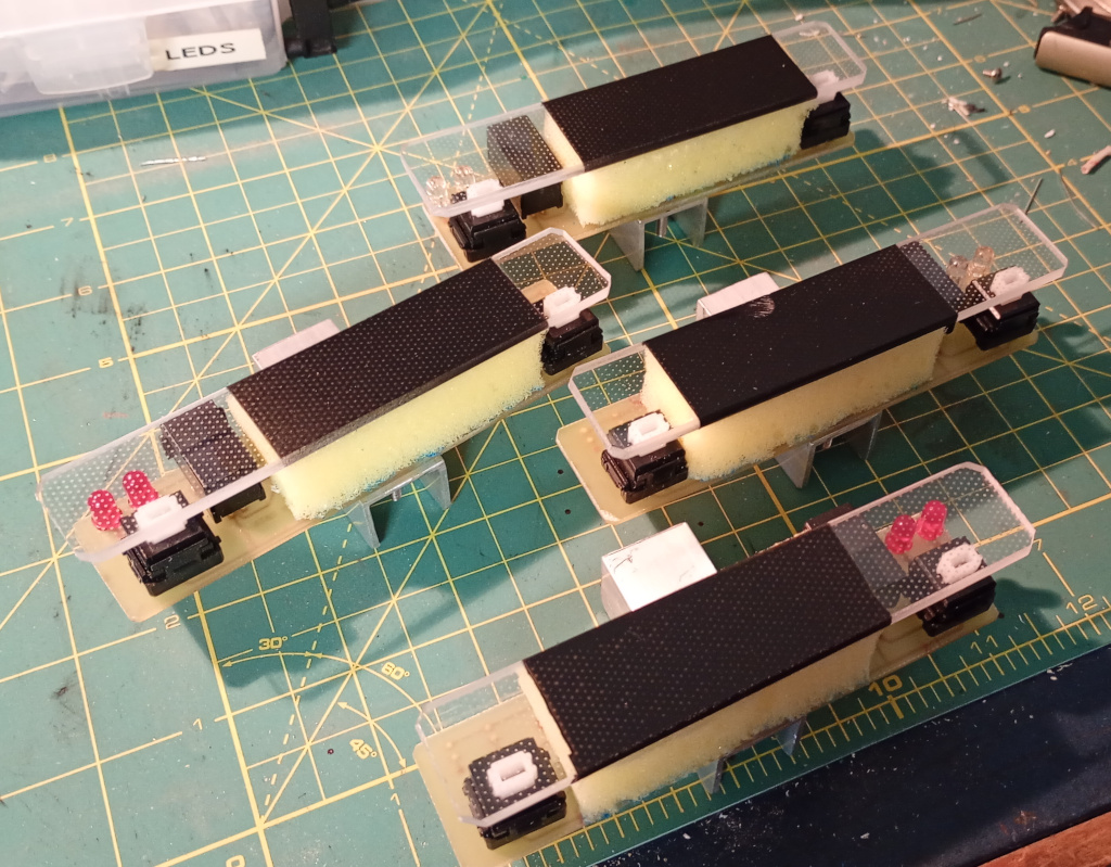
Today I spent all morning finishing off the bumpers for the new robot. I decided to try using acrylic for the actual bumpers, so the first task was to saw them out of the sheet. Fortunately the sheet had a bit that was the perfect size for the job, so after measuring up the four slices I took to it with the hacksaw, then finished them on the sander.
I was planning to use my usual construction technique which involves mounting the bumpers to a foam pad. That allows for the physical deformation in a collision so that the contact switches can be activated. I wasn’t keen on the idea of having the foam pad be visible from the front, as it is attached with glue and likely to look a little rugged. I elected to spray paint over the contact region but leave the rest of the bumpers clear. The result can be seen in the image above.
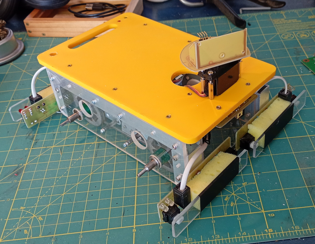
After gluing the foam and bumpers to the circuit boards and leaving them to dry, I installed the bumper modules. At the same time I cut down some threaded hex standoffs to about 7mm long. I used the shortened standoffs to mount the main circuit board.
The new position of the circuit board meant that the wires to the status LED board were too short, so I replaced that wire with a longer piece. I also terminated a length of ribbon cable to connect the main board and the motor control board.
I still need to rig up cables to connect the sonar module to the main board but other than that there is not much else to do on the main design, beyond installing the microcontrollers and the power management..