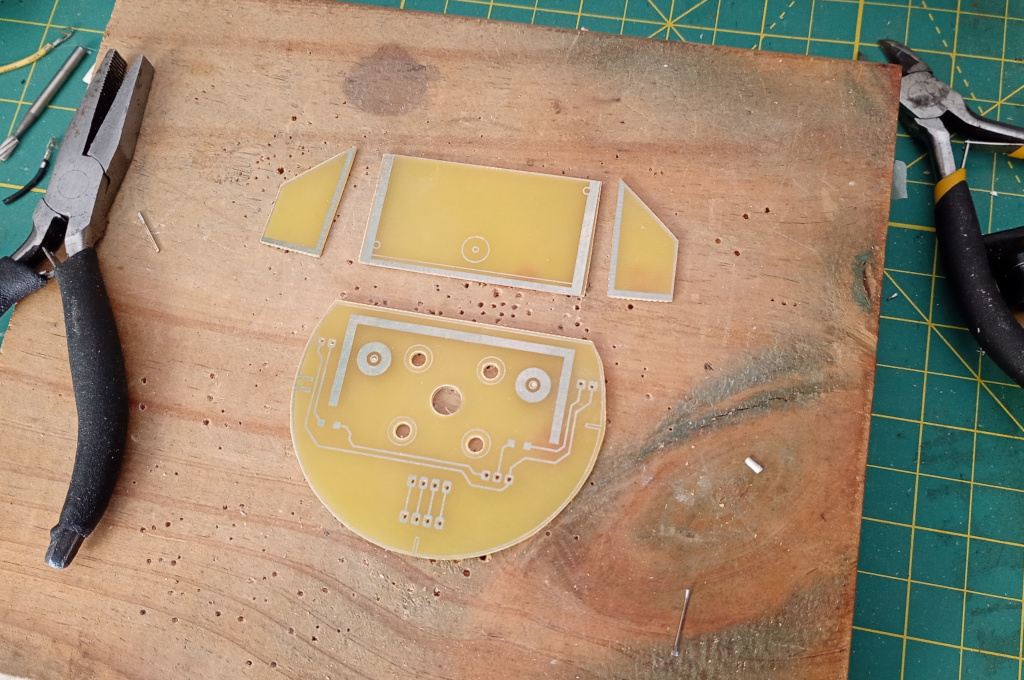
I did a bit of work on the sonar deck for the robot. The first task after cutting out the boards was to solder the component pieces together. I use PCB material for the mechanical structure of the deck and include traces for electrical connections. The way it turns out means that any electronic components need to be reverse soldered, but that’s not an issue.
This version of the board was designed to allow a 3.3v sonar module to plug straight into the Pico. Unfortunately, as I already mentioned, I ordered 5v modules. So I needed to figure out a way of reducing the voltage of the echo line to 3.3v.
I hunted around in my box of resistors until I found 3k and 4k7 resistors. I’d only just harvested them from the old TV circuit boards. Anyway, those resistors end up providing around 3v from an input of 5v.
The echo line, which is the second from the right of the set of 4 parallel tracks, had to be cut so that I could solder the 3k resistor in line, then I had to solder the 4k7 resistor between the echo line and ground. You can just about see the resistors between the header pins.
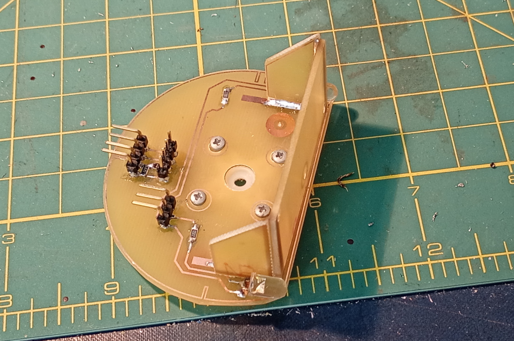
While I was messing about with the voltage divider I decided to fully populate the board. I tried to solder on some white LEDs that I had salvaged from old garden lights but even after cleaning up the leads I had a hard time getting the solder to wet cleanly. Anyway I splooged a lot of solder onto the joints and they test out okay but man! Soldering dirty old leads sucks.
You can sort of see the servo mounting hardware screwed underneath the deck and for once I got all the screw holes aligned with the holes in the servo horn.
I decided to check the actual output of the echo pin because theory is all good and well, in theory. I stuck 5v across the module side echo pin and ground and measured the voltage on the Pico side echo pin. Sure enough I got a good 3v, verifying that the voltage divider was working.
I also repeated the test for the 18v battery test circuit. That also has a voltage divider to reduce the battery pack voltage to something the Pico can monitor. I got a safe reading of 3v there too, so maybe I won’t fry my Pico.
If I do another version of the sonar deck I am going to add pads for the voltage divider resistors. Maybe I’ll unify the sonar and LED circuitry, because as it is I’m not sure how I’ll get power to the LEDs, given that I made the PCB with separate connectors when 5v and ground were right there.