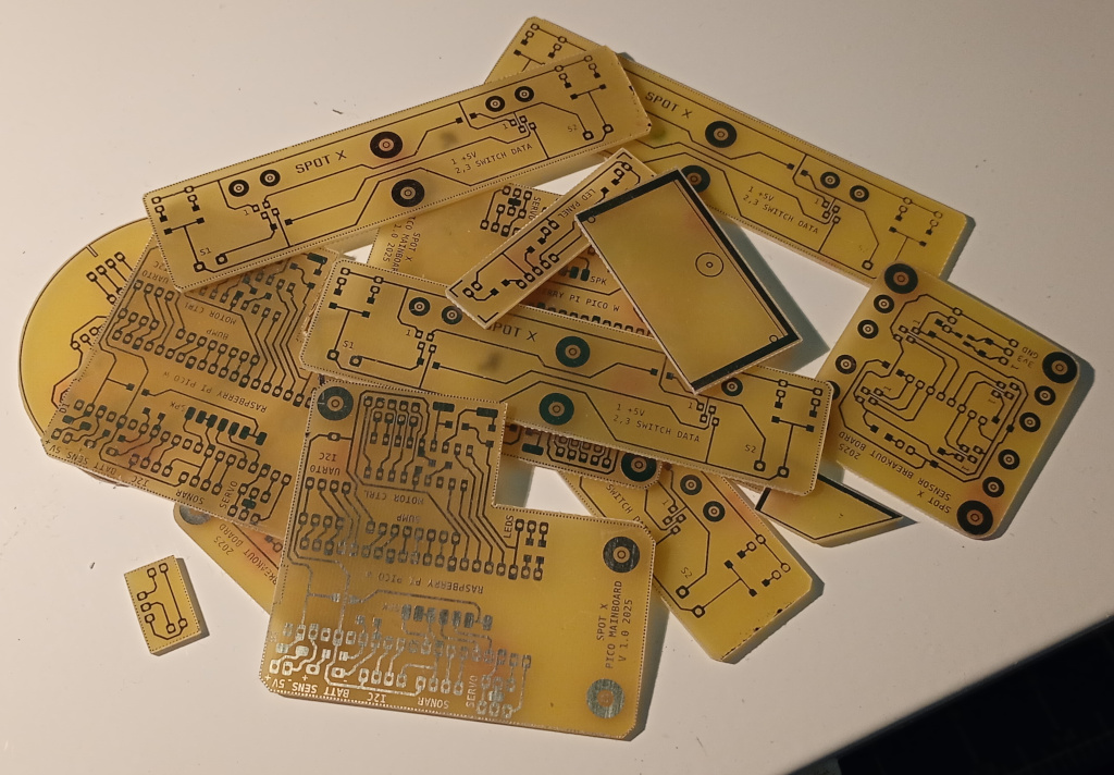
I spent most of today making up the boards for my new robot and, oh boy! Maybe it’ll be fine.
I started the day trying to figure out how to best use the space in the blank PCBs. The supplier didn’t have any of the stock I normally use, so I am using 300mm x 150mm boards that I cut in half to make 150mm x 150mm boards.
Exposure and development went smoothly enough although I suspect that one of the boards I made wasn’t in close contact with the transparency, because the traces got noticeably fuzzy and eroded on one side.
My printer is not good for this application. The little metal teethed rollers track ink in places, leading to tiny flicks of ink where it shouldn’t be, sometimes leading to short circuits or breaks in the track. It’s really frustrating because it doesn’t happen on paper.
All this to say that the printing and photo transfer stage is fraught with difficulties I never had with the Epson Stylus 3000 or the laser printer.
Anyway, I mixed up a batch of brand new etchant and wow! The etching was done in just a few minutes. I can’t complain about the etching although I did notice holes in some of the copper areas, but that’s because of the poor quality of the transparencies.
The next step was to cut the boards up with the hacksaw. I also used a tiny end mill to make cuts that I couldn’t get to with the hacksaw because of the way I’d laid out the boards. Once the boards were separated I sanded down the edges and vacuumed up the fibreglass dust.
My practice is to punch each of the holes before drilling to stop the drill from wandering. I sharpened a punch to a point and sat tapping away on the boards I really wanted to make up. By this stage I was feeling a little tired, so I never the job but instead got on with some drilling.
It’s not easy these days, with my eyesight being what it is and all. The punched impressions help seat the drill tip but even then I’m not so good at getting the drill in the right spot. Anyway I did a bit of that until once more getting tired of it all and giving it away for a bit.
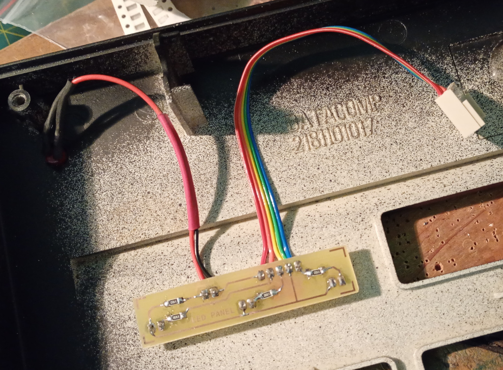
Eventually I sat down and began soldering up one of the boards —the status LED PCB for the keypad I was making. I was still uncertain whether it would fit in the available space but I put it in place without soldering it up and all seemed fine so I collected the components and began soldering. I used 330Ω SMD resistors and some LEDs, soldered on some ribbon cable, terminated it and soldered the Power LED lead.
I got the power LED reverse biased, so after fixing that everything seems fine. I’ll swap the Caps Lock and Num Lock LEDs and dim them down with PWM, but other than that, the big keypad is pretty much finished, aside from labeling the keys.
Now I need to get some more Raspberry Pi Picos to get the robot working.