I found out there’s such a thing as beige PLA and there was only one thing to do in response: I made a retro computer, Well, when I say I made a retro computer, what I mean is I made a model of a retro computer.
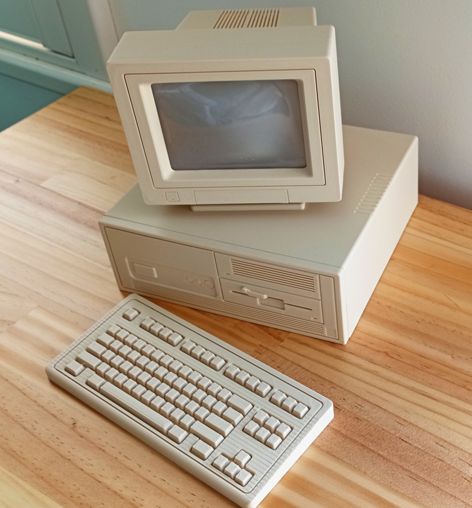
It was largely an experiment in Blender that evolved. Having bought the plastic I started messing about in Blender and soon had a reasonably well fleshed out retro computer case. I split the mesh into the front and rear panels and the top of the case. I printed the front and rear panels as a test to see how they would turn out and they came out really nice. So nice in fact that I then had the problem of knowing what to do with them. I hadn’t really thought very far ahead and the design wasn’t actually practical as a useful case.
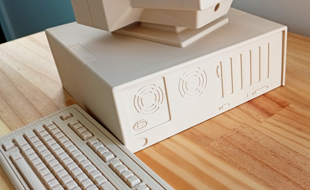
I ended up printing the rest of the case and gluing the front panel to it. For the rear panel I fiddled about and managed to create some modifications that let me attach a sheet of steel. The rear panel and the steel sheet slide into the case so that the interior space is accessible. It works, for what it is but I’m working on a modified design that’s a little more practical.
For the keyboard I got a picture of an IBM keyboard and used that as a template. It wasn’t all that complicated.
The monitor posed its own set of challenges. The trickiest part was the screen. I didn’t want to print the screen but I needed to come up with a way of manufacturing it. I built a little wooden box with the right dimensions to act as a vacuum forming chamber. I had a lot of diffuser plastic that I got from old TVs that was smooth on one side. The vacuum box has a lid to retain the edges of the plastic while allowing me to heat the middle of the plastic. My first attempt sort of worked, but the vacuum was too strong and sucked the plastic in too far; I had hoped to simply use the natural sag of the plastic without any mould, but that didn’t work. It’s super important to get the plastic uniformly hot over its entire surface otherwise it deforms unevenly. I had another go, this time I heated up the plastic and rammed in a printed mould. It sort of came out not too bad. Again, it wasn’t even, owing to uneven heating and probably technique but fitting the sheet of plastic into the bezel, it looked passable.
I glued it into place and there you have it.
Ideas for improvement.
This was never meant to be anything other than an experiment. So it has its faults. But I think I can make some modifications that can turn this from an experiment to a workable product. First is to modularise the case design elements, by which I mean create a tight base design and split the decorative elements into separate boolean tools that can be repositioned as needed.
Second is to create a workable solution for the mechanics of the case. This will involve solving the issue of the base and attaching the rear of the case. I’m thinking of designing a printable base that PCB mounting stubs can be added to. That way I can add electronics to the case to make it functional. The printed base will also include mounting geometry for the rear panel; the front panel works well as is – glued onto the body of the case, although there’s no reason not to add screw attachments. For the case, I see this being a base design that can be modified for other actually practical uses.
I’ve already made improvements to the design of the monitor. I’ve added positioning widgets on either side of the front bezel to keep it centred on the body of the monitor. With the current design it wobbles sideways a little. If I make another screen I’ll alter the profile. The design I used was too deep and just didn’t look quite right. Obviously the real modification I want to add is, well firstly an array of Blinkenlights inside to simulate a display. Operated by a microcontroller I reckon it could look neat as a moving light show. But secondly I want to add a functional display. There are any number of Raspberry Pi compatible screens available. I just need to get one that I can build around. The problem is that some of them have the HDMI connector on the side of the panel and that would mean figuring out a solution to that. Also I would need to add the necessary mounting points – in short a complete redo of the monitor. But I think it could be awesome. Also, the monitor stand could be redesigned to tilt, since the current design doesn’t tilt.
Anyway, this was a fun project, only slightly marred by being compromised by the sunk cost fallacy of having to put together the model around elements that were not designed with assembly in mind