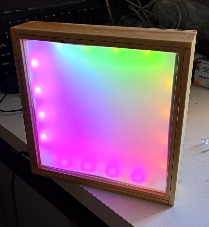
Well I finished the light box I was working on.
It’s taken me, what, 2 months or so but I’ve got the firmware loaded and it runs. So let me expound.
While I was working on the kitchen shelves, I ended up with some strips of pine that didn’t work out as edging for the lazy susan shelves. I decided to try to make something with them.
Carefully cutting them to size and cutting the joints, I ended up with a square timber box. I decided that I could fit the inside with LEDs, left over from when I made my bedside lamp. I’d originally planned to use a PIC for that purpose, but in the meantime I had purchased some Raspberry Pi Pico Ws.
I managed to fit the Pico into the box, but in testing I discovered that trying to run a pile of RGB LEDs off the Pico was not a good idea.
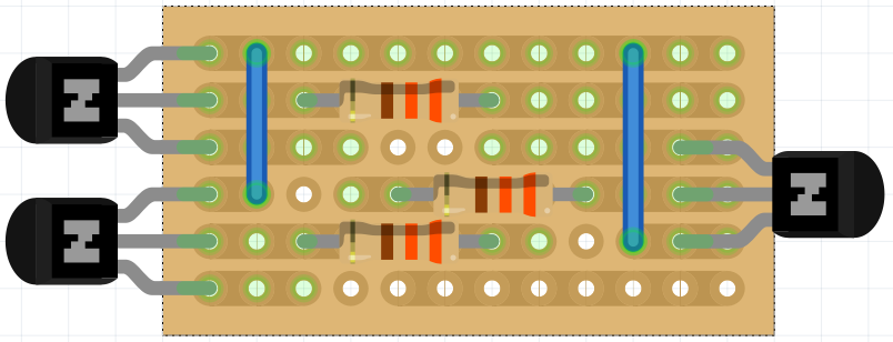
I opened up Fritzing and created a simple LED driver circuit using Vero board. It uses a bunch of BC548s to switch the 5v from the USB connection.
I built 4 of these and fitted them inside the box. Each module controls one strip of 4 RGB LEDs. I also added a push button for manual control of the Pico.
In testing, I discovered that I couldn’t simply use any random pins to drive the LEDs with PWM. The PWM circuits of the Pico consist of, uh, anyway, you can’t PWM on one pin and then try to PWM on certain others because they share the PWM circuitry, and also the frequency circuitry is shared, or something.
Anyway, after soldering up the Pico as I wanted to, I had to desolder it and use 12 pins from 0-14.
Testing further revealed that the red LEDs on one of the strips wouldn’t light up. It turned out that one of the transistors was faulty. After replacing that all the electronics seemed to work.
I created a cardboard insert that slides in from the front with sides that fold up to hide all the wiring. It also serves as a reflector, improving the light output and the LED strips are stuck directly to the flaps.
I tried using double sided tape to stick the flaps to the timber, but it hasn’t worked totally well and you can see some gaps where the flaps don’t sit straight against the edge of the frame. If I do it again I’ll angle the sides of the insert so it kind of bevels.
I fitted a sheet of diffuser plastic and rigid polycarbonate that I salvaged from one of the old laptop screens. Cutting the polycarbonate is tricky, but I managed it with a sharp knife and lots of cuts. No sawing. No snapping. On the back I screwed a piece of plywood. It works but it’s a bit ratty. I think if I modified the frame, the plywood could sit inside a rebate or somesuch.
So there it is. The hardware complete. Now I had to program it.
Originally written August 13, 2025