It looks pretty much like the old Spot X, but I just finished building this one. 12 years later.
I’ve had the hardware bashing about in the shed for more than a decade, since I pulled apart most of my Spot 9 robots. On a whim I decided to build a new robot and put those parts to use.
I rummaged around and found the motor modules and pulled them to bits, found a couple of bearings I needed and gathered the rest of the materials.
One thing I didn’t have was the aluminium rails. Oh I had rails but they were for Spot 9 and looked pretty messed up. I went shopping for 20mm square section Al tube at Bunnings but they didn’t have any! So I settled for C-section which works fine.
I found the old drawings of the Spot X hole patterns, fiddled with them in Inkscape for a bit and managed to do a pretty good job with the machining. For the deck I elected to use threaded brass inserts that I’d salvaged from old computers.
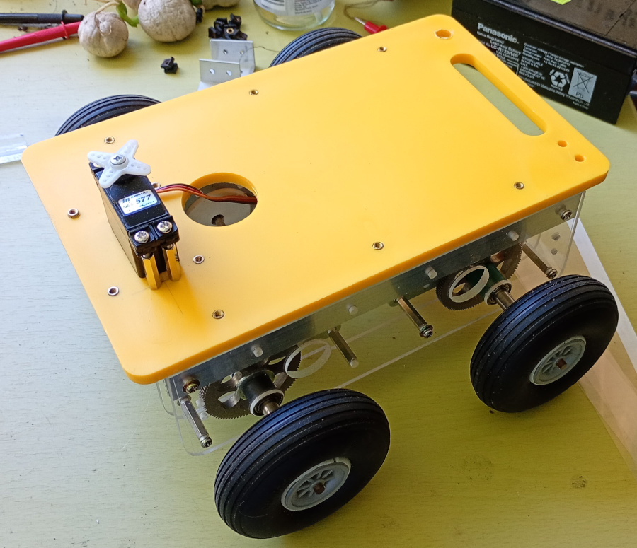
Not having a servo to hand I went down to the shed and got my old model plane and ratted the servos out of it. The plane was not in good condition and so I might as well get some use out of the servos.
I accidentally drilled the access hole too close to the front, so I had to mount the servo sideways, which also works.
The motor driver is mounted underneath, just like the old Spot X but I’ve taken a bit of care with the cable management, so it’s a bit tidier.
Now I’m figuring out the motor control, power and main control board options. I’d designed a swish new board with KiCad that I was all set to send to PCBWay before coming up against the design constraints of fitting the design into the undercarriage space. Now I’m not sure how I should proceed. I’m not confident of getting it to work.
Adding to the space constraints, the PicoW requires certain copper free spaces on the PCB for the WiFi transmission and that uses a lot of the available width.
Also, getting the design made by PCBWay still leaves ancillary PCBs to be constructed, such as the bumper boards. I’m leaning towards self constructing the boards I need, just because of the cost, even though commercial boards would look great.
I’m also weighing up the power and display options. I think a buck converter module will be more suitable than the 7805 based circuit I have used since forever. I would also like to incorporate some battery monitoring, since I’d like to use Li-Ion battery packs and don’t want to destroy them.
So, maybe a redesign of the circuit board is in order. I’ll map out a footprint and do some clever stuff. Maybe it will even work.
Originally written September 17, 2025