I was rooting around in my box of goodies the other day when I came across this old keypad and thought why not get it working?
It’s made from the numpad section of an old keyboard that I got when I cleared away all the old computers from a local High School. I had so many old AT keyboards that I ended up harvesting them for switches and cables.
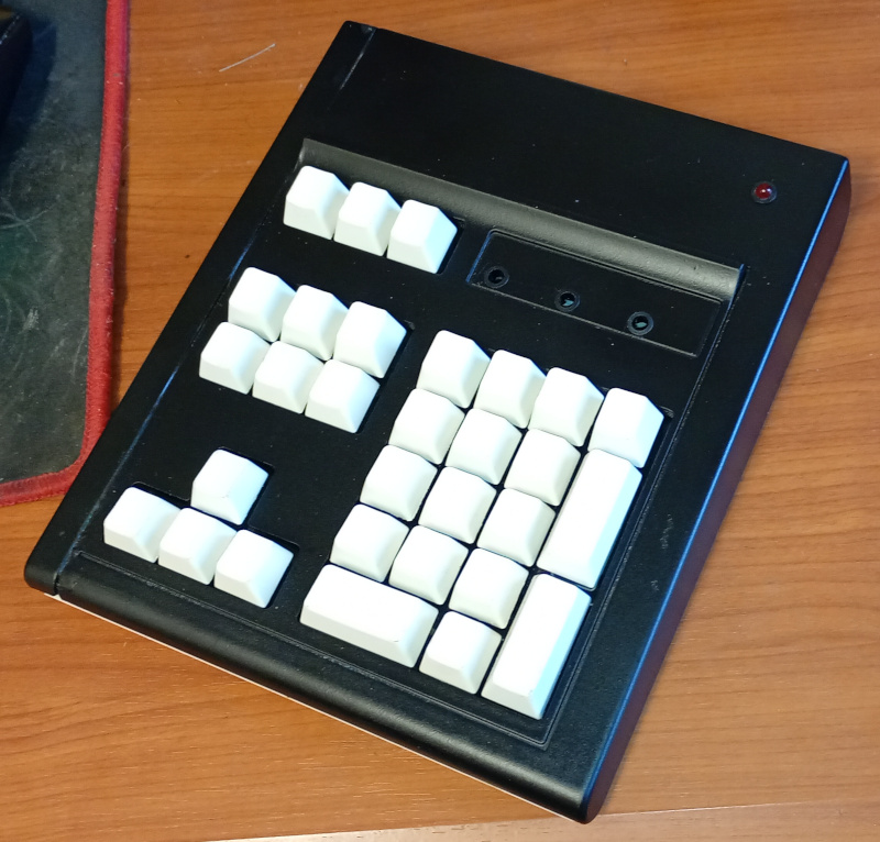
But anyway, this was one of at least two that I made into mini keypads using the original cases cut and glued.
The keypad was fitted with a PIC based driver circuit but the PCB for the actual keys was separate and I figured it would be easy enough to fit a Raspberry Pi Pico inside and turn it into a working USB keyboard.
Mechanics
As it was, the two halves of the case were held in place with the original case screws on one side and taped with electrical tape on the side I had chopped. I wanted to dispense with the tape, so I needed to find a way to add screws. I ended up managing to epoxy a couple of threaded hex PCB standoffs inside the case and drilled through the bottom of the case to allow screws. It works fine but isn’t perfect because I can’t screw the rear edge tightly – the hex space doesn’t span the internal space between the top and bottom halves of the case.
I also needed to figure out how to fit the Pico. It’s so small that mounting it is a challenge. I settled on using tiny screws to fit it to a piece of timber that I hot glued inside the case.
I used a craft knife and a file to create an opening to allow the USB cable to plug in. That worked out fine.
The case was originally beige, but I’d spray painted it white long ago. It was looking a bit tired so I sanded it back a bit and gave it a coat of black paint. Looks fine.
Wiring
I unsoldered the existing PIC board and soldered header pin plugs to the cables. There wasn’t space enough to use vertical header pins so I used 90° pins.
While I was inside the case I noticed that the original design included space for a speaker. I decided to take advantage of that and installed a small speaker, although I haven’t yet figured out how to make the Pico make noise.
The case had holes for LEDs (Caps lock, num lock etc) so I enlarged them enough to accept a 5mm LED bezel. I have a PCB designed that I will try to fit, but I’m not sure there’s enough room for it, so the LEDs may or may not be something that happens. I did add a power LED and that should work, even if it’s the only one.
Programming
Well I thought MicroPython would have the libraries I needed to implement a HID keyboard and the documentation said it did but I couldn’t figure out how to install it, so I flipped over to CircuitPython. I loaded the test program and got the Pico operating as a keyboard pretty easily.
The thing is, I wasn’t using discrete switches. My PCB uses an 8 x 4 array so I needed to implement an array scanning algorithm. That was achieved with a couple of FOR loops. The current limiting resistors for the columns were already incorporated into the keypad PCB and the pullup resistors for the rows were replaced by internal pullups in the Pico.
After tracking down a couple of bugs I had a running program that scanned all 30 keys and sent key presses back to the PC. Then came half an hour of tracking down the actual key codes I needed to send so the keypad was actually usable.
I’m not sure about the numlock functionality. I might need to program that separately. Also I suspect that the keypad won’t respond to numlock changes using the main keyboard. Still, I think I can get num locking working okay with a bit more code.
To Do
I don’t need the keypad to spawn a window every time it is plugged in, so I’ll have to investigate how to suppress that behaviour of CircuitPython.
The LEDs are not wired in yet, so once I make the circuit board I’ll have a go at that.
The keys are blank. That’s a little awkward. Maybe I can use the Dymo and make some labels or print some on a clear label. The Dymo works pretty well but we will see.
I’d like to try some different key mapping options. Not sure what, but I could use it for…dunno. Something really useful. Than again my main keyboard already has macro keys that I’ve never used.
Conclusion
I think the project came out pretty well. The existing PCB is in excellent condition, for being possibly 20 years old. I’d like to know where my other big keypad got to. I know it existed because I have pictures of it. Maybe there’s another box of goodies. Yeah, nah. I know exactly what happened to it.
Addendum
So, it’s after tea now and I’ve spent an hour or so messing with the speaker. Getting the sound to play was as simple as creating a PWM output and getting it to play for a split second whenever the key status is changed, i.e. when the key is pressed.
I took the opportunity to add some silliness. The program checks whether certain keys are pressed and changes the pitch. There are 3 sounds: beeps, boops and borps. Most keys boop, some of the command keys like Enter beep and just a few borp. I am considering adding a switch to turn off the speaker.
I also found out that autorepeat works out of the box, as does the numlock functionality. It even picks up when I change the numlock state using my main keyboard. Not sure about how to get access to that info to set the numlock LED. Actually, that seems pretty straightforward too, because the keyboard class includes ways to get the status of the LEDs and use that to set physical LEDs on or off. I haven’t hooked the LEDs up yet but I think I’ve got the code all sorted.
Originally written September 29, 2025