I couldn’t find out how to add a caption to the picture. [But now I figured it out …Ed.]
I was fiddling with one of the old robot keypads and, same old story, thought I might like to upgrade the hardware so it could be used as a USB keypad. But as I tried different ideas, it became apparent that the existing cases aren’t suited to retrofitting a Pico into them, because of the spacing of screws and whatnot.
I’d already machined a replacement end for the existing box and thought the design theory might work as the basis for a brand new box.
There were plenty of scraps of timber lying about and I eventually located the pieces I needed. The front and back were made from 12mm pine and the sides were made with strips of 6mm pine.
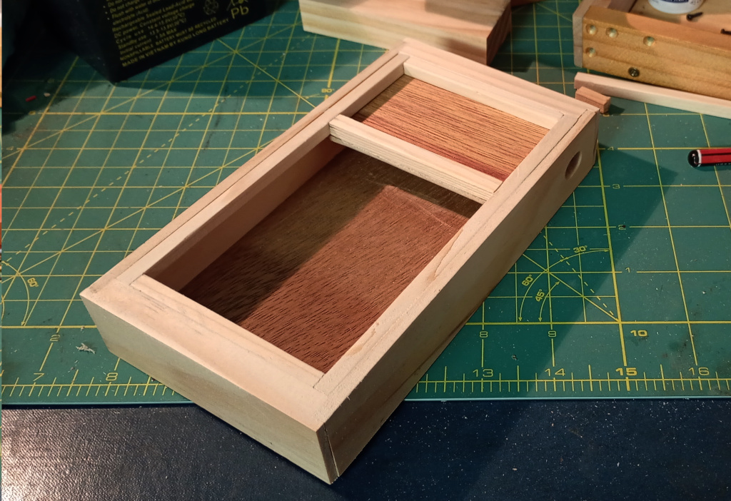
I sawed a trench in the front and back pieces to accommodate the plywood I used for the base and added strips underneath to prevent any flexing of the base.
The case needed a hole for the USB cable and this time I machined it with a Forstner bit with the drill press set up with brackets to make sure everything was square. Other than the pine being characteristically weak and crushing a little, the slot came out quite well.
This is also not a caption
The top was made from pieces of 6mm square pine with a piece of plywood. The entire box is glued together and the top sits held in place by the sheer force of my amazing skill at cutting it to the perfect size.
Preparing and Mounting the Electronics
I had only one Pico left and I’d already soldered header pins onto it, so they had to come off. The keypad that I was employing incorporates a PIC microcontroller on the board, so I desoldered that and the other electronics so that I had access to the row and column connectors.
I soldered wires onto the keypad PCB and added a separate decimal point button. The original design did not have the decimal point hooked up, because I was using a 4 x 4 matrix. With the added GPIO pins of the Pico it wasn’t hard to add in the extra key.
After a bit of head scratching I decided on a way to mount the Pico and the keypad. It was very tight for room, so I had to settle for a smaller speaker than I had wanted.
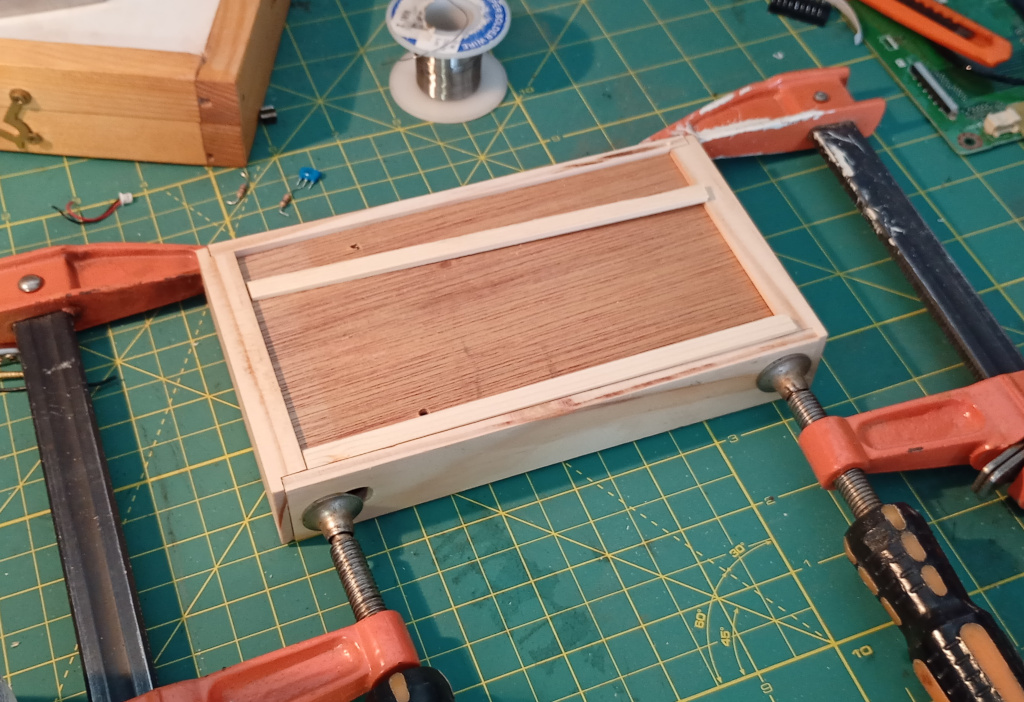
Figuring out how to install the keypad status LEDs proved to be a challenge. At first I thought of using the LEDs with silver bezels, but they were way too big. Black plastic bezels didn’t fit the aesthetic either. Eventually I elected to subdivide the plywood lid space with a sliver of pine into which I set 3mm LEDs that I’d salvaged from my old evaporative cooler, carefully spacing and countersinking the holes. By chance I chose 8mm spacing which kinda almost perfectly worked, because I hooked up the LEDs to a piece of perfboard and the leads fitted.
I soldered all the wires to the Pico directly, owing to space constraints and brought the keypad inside for programming.
Programming
I already had the program from my previous keypad project so most of the work was done. I say most of the work was done. I ended up restructuring it.
The program needed tweaking to account for the lower key count, different pin assignments and so on. The real trick was how to poll the decimal point key which was not in the matrix.
At first I simply copied the code that dealt with scanning the matrix keys but soon realised that the code was similar enough that it’d be better moving it to a function.
I moved the bulk of the program into main() and took the key test code into a new function called testKey() that takes a GPIO reference and a key index and does all the HID keyboardy stuff.
And it worked.
As I suspected, the status LEDs were simple to set using the keyboard.led_on() method in the HID API. I had a little trouble synchronising the status LEDs with the main keyboard when plugging in the keypad. This was solved when I copied over the boot.py script IDK why.
Speaking of, I changed boot.py to read the + key on boot to allow the user to mount the Circuitpy USB storage drive.
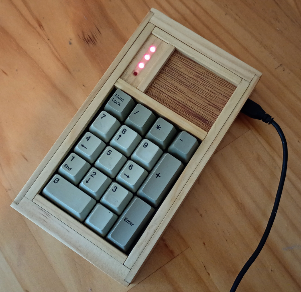
The LEDs were super bright, even running at 3.3v with 220Ω resistors. I changed the LED pins to PWM and set their duty cycle to 4096. That gives them a gentle red glow that isn’t dazzling.
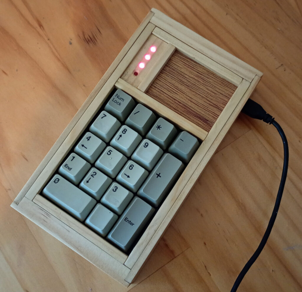
And here it is. I’ve set the LEDs to display power on, num lock, caps lock and scroll lock, but I’m changing scroll lock to compose, because I can’t get any LED response from scroll lock.
You know, I’m kinda happy about this. That keypad is close to 20 years old and it includes components from a keyboard that would have been maybe 25 years old, perhaps older, if I hadn’t murdered it.
It sucks so much that we take so much perfectly good stuff and just throw it in the trash. And the new stuff we buy is even more enshitified than the stuff we tossed out. It doesn’t make sense.
Originally written October 5, 2025